- Review
- Open access
- Published:
A review of the applications of fuel cells in microgrids: opportunities and challenges
BMC Energy volume 1, Article number: 8 (2019)
Abstract
Since the last two decades, microgrid, as one typical structure in smart grid framework, has been receiving increasing attention in the world. Meanwhile, fuel cell (FC), as one promising power source, has redrawn the attention of both academia and industry since the beginning of 21th century. Some encouraging achievements in FC technology have been realized thanks to the efforts taken in the last years. Due to this, it is seen that FC, as a clean and efficient energy source, is penetrating into different fields. Among the applications, integrating FCs into microgrids has shown interesting advantages on improving the performance of microgrids and promoting the use of the hydrogen energy. Some ongoing projects have shown that FCs of different power scales can be integrated into microgrids smartly and in different manners. Along with the advantages carried by the combination of the two technologies, many challenges lying on multiple domains are faced in the process. The challenges can be from the FC, the microgrid, and the integration of these two technologies. In this review paper, the advantages of integrating FCs into microgrids are summarized after recalling the knowledge background of FC. The challenges and ongoing researches on FCs and FCs based microgrids are then reviewed. Based on the analysis, the research directions are then extracted in view of the challenges.
Introduction
With the urgency of offsetting the fossil fuel depletion and reducing the greenhouse gas emission, a worldwide effort has been made during the last decades. The European Commission has set its 2030 targets for the promotion of renewable energy sources (RES) inside the European Union (EU). The main goals are to achieve a 40% reduction in greenhouse gas emissions compared to 1990 levels, at least 27% share of EU energy from renewables, and at least 27% improvement in energy efficiency [1]. Similarly, the United States Department of Energy (DOE) has also set its RES target as 27% of renewable energy share by 2030 [2]. Meanwhile, the China’s National Development & Reform Commission (NDRC) has set a draft policy to increase the RES target from 20% to 35% by 2030 [3].
Nevertheless, with the high penetration rate of RES in an uncoordinated way, many technical and operational challenges may emerge, such as the deteriorated voltage profiles, reduction of frequency reserves, and congestions in transmission line [4]. Microgrid provides a promising and efficient solution by integrating various distributed RES (e.g. photovoltaic panels, wind turbines), energy storage systems (e.g. batteries, supercapacitors and flywheels), and interconnected loads that acts as a single controllable entity with respect to the utility grid [5]. According to US department of energy (DOE), a microgrid was defined as "a group of interconnected loads and distributed energy resources within clearly defined electrical boundaries that acts as a single controllable entity with respect to the grid. A microgrid can connect and disconnect from the grid to enable it to operate in both grid-connected or island mode" [5]. With a proper design and control, it can supply good-quality and high-efficient electric power, reinforce the grid reliability and supplement the main grid to supply electric powers to remote and islanded areas.
Currently, a wide range of RES can be integrated into the microgrids, such as wind, solar, fuel cells (FCs) hydroelectric and biomass. Among these technologies, FC is gaining an increasing popularity in microgrids during the last decade [6–8]. It converts the chemical energy from a fuel, typically hydrogen, into electricity through a chemical reaction without internal combustion, and with only water and heat as by-products. The integration of FCs in microgrids has been demonstrated to be a promising solution as it can provide reliable, efficient, clean and quiet energies. Generally, according to the role of FC, four application markets of such microgrids can be categorized: primary power, backup power, combined heat and power (CHP) and FC vehicles [9].
Despite the numerous advantages, the integration of FCs into microgrids can pose several key challenges as the two cut-edge technologies are combined. On the one hand, FC technology has not yet widely commercialized, although increasing attention has been paid to overcome the drawbacks in FCs, i.e., low durability and high cost, from different perspectives [10]. On the other hand, the system hybridization, the system control and the energy management problems have raised up as the requirements on reliability, resiliency, and safety of the microgrids become more and more critical [11–13].
This paper aims at reviewing the recent advances in FC and microgrid technologies. The representative studies have been discussed to provide the insight for the researchers working in different domains to have an global idea. In the first section, a background of FC is introduced, including FC principles, different types, system composition and the state of its development. The second section emphasizes on the applications of FCs in microgrids, with its advantages and application types summarized. Challenges of applying FC technology in microgrids and possible solutions are summarized and discussed in the third section, followed by a conclusion and prospective in the last section.
Background of fCs
This section is dedicated to presenting the FC basis and the content is mainly adapted from the work in [14].
Fuel cell principles and types
FC is a device that converts the chemical energy from a fuel (hydrogen is the most common fuel) into electricity, heat and byproducts (generally water) through a chemical reaction with oxygen or another oxidizing agent. Hydrogen and FCs offer a broad range of benefits for the environment and the balance of the energy structure. Due to their high efficiency and in-situ near zero-emission operation, FCs have the potential to drastically reduce greenhouse gas emissions in many applications [15]. Since hydrogen can be produced from diverse sources such as renewable resources, biomass-based fuels, and natural gas, large-scale using of FCs can slack the dependence on the fossil fuels, and advance the renewable power development [16].
A variety of FC types, which are distinguished by the electrolyte that is used, have been studied since the last century. Basic information about these FC types can be summarized in Table 1 [17].
Among the variety types, Proton Exchange Membrane Fuel Cell (PEMFCFootnote 1) has drawn the much more attention from both academic and industrial institutions owing to its simplicity, viability, quick start-up and wide power range. In this review, the main focus is put on PEMFC due to two considerations. First, the PEMFC is one of the most studied FCs in the literature, and the problems of PEMFC are often representative and involve other types of FC. Second, the review paper provides the analysis on the FC system and microgrid levels, and the difference among different FC types has little importance in the system level discussion. In the rest of the paper, FC is specific to PEMFC without particular underlining.
From single fC to fC system
As Fig. 1 shows, from the middle to the both sides, the different components can be described as follows [17]:
-
Membrane
Fig. 1 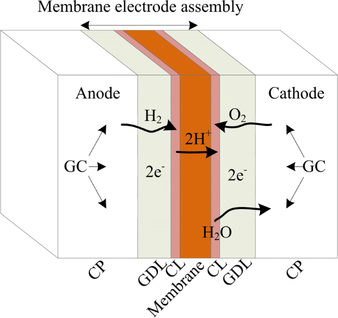
The basic principle of PEMFC operation
Polymer membrane, which acts as the electrolyte, is the heart of FC. It is impermeable to gases but it conducts protons.
-
Catalyst layers (CL)
At the two interfaces of the membrane there are the layers with catalyst particles. The best catalyst for both the anode and the cathode has been the platinum. The catalyst particles are supported on larger carbon particles.
-
Gas diffusion layers (GDL)
The polymer membrane, with catalyst layers settled on the two sides, is sandwiched between two sheets of porous layers, which are called GDLs. These layers are typically made out of carbon cloth or carbon fiber paper. One of the functions of GDLs is to allow diffuse of both the reactant gases and product water. Besides, GDLs also perform as the electrically conductive electrodes and the heat-conducting mediums. The membrane, CLs, GDLs are usually combined together as the membrane electrode assembly (MEA).
-
Collector plates (CP)
The CPs are settled on the two external sides of a PEMFC. Gas flow channels (GFCs) are grooved on the one side or the both sides for gas flow (one-side channels are shown in the figure). The CPs can not only house the GFCs, but also act as the electrically conductors and heat conductors. Moreover, they provide structural support for FCs.

A running FC is usually fed continuously with the hydrogen on the anode side and with the air on the cathode side. Electrochemical reactions occur at the surface of the CLs. On the anode side, hydrogen is oxidized:
Protons travel through the membrane, while the electrons travel through the CLs, the GDLs, and the external electric circuit where they perform electrical work and return to the cathode side.
With the protons transferred through the membrane and the electrons through the external circuit, the oxygen is reduced on the cathode side:
Combined the reactions on the anode and cathode sides, the global reaction is
With the conversion of chemical energy to electrical energy and heat, the by-product water is generated and expelled mostly with the unreacted air from the cathode side.
The maximum amount of electrical energy generated in a FC corresponds to Gibbs free energyFootnote 2. In the reaction (1), denoting the difference between the Gibbs free energy of the products and the that of reactants as ΔG (expressed in (eV) for one mole H2O), the theoretical potential (ideal voltage) of the FC corresponding ΔG is
where F is the Faraday’s constant. This gives a value of about 1.2 V for a FC operating below 100∘C [17]. However the voltage of a practical FC is usually less than this value. Voltage losses in an operational FC are caused by several factors.
As Fig. 2 shows, the distance between the real open circuit voltage and the ideal output voltage is caused by the factors such as the crossover of the reactants. The curve that characterize the relationship between the voltage and the current is named polarization curve. Three main factors that impact the voltage losses are [17, 18]:

Various voltage losses and polarization curve of an operating PEMFC
-
1.
Activation losses. This part of voltage is lost in driving the chemical reaction. These losses depend on the catalyst material and the micro-structure of MEA, reactant activities, and on current density.
-
2.
Ohmic losses. This category of voltage losses is caused by the resistance associated to the electrodes, the electrolyte, and other interconnections. Ohmic losses are proportional to the current density. Besides, the material and the structure of the FC, and the temperature can impact this kind of losses.
-
3.
Concentration losses. These losses result from the drop in concentration of the reactants at the surface of the electrodes, and depend strongly on the current density, reactant activity, and electrode structure.
The effects of the three factors are easy to distinguish. Activation losses, ohmic losses, and concentration losses predominate respectively in the zones I, II, III shown in Fig. 2 [19].
When drawing a useful current, the voltage of a single FC is about 0.7 V, which is too small in most cases. In order to produce a more useful voltage or power, many cells have to be connected in series, which functions as a FC stack. In practice, the cell interconnection is usually achieved by using the bipolar configuration. As Fig. 3 shows, bipolar plates (BPs) are the CPs installed inside the stack. GFCs are grooved on the both sides of BPs. This makes connections all over one cathode and the anode of the next cell. Meanwhile, the air and hydrogen can be fed to the cathode side and anode side of two neighbored cells.

Schematic of PEMFC stack
Auxiliary systems and power converters
Often FCs are compared with different batteries. Fuel cells are considered even by some people as one special type of “battery". However, the FCs differ from battery in many ways.
A FC stack is obviously the heart of a FC system, however, the stack itself would not be useful without auxiliary supporting subsystems. Apart from the stack, the practical FC systems involve the following subsystems:
-
Air supply subsystem
The objective of the air supply subsystem is to supply air with proper flow rate and/or pressure to the cathode of FCs. Air is usually provided by a blower or a compressor, which is located at the air inlet. By regulating the blower or compressor, sufficient air can be maintained to keep the desired cathode stoichiometry flow rate over the full power range. The proper Sc can make the stack operate in an optimal and efficient state; while insufficient air flow cause degradations or even damage the stack in severe cases.
Another function of air supply subsystem is to supply a proper air pressure for the FC stacks. The pressure at the air inlet is generally pressurized from slightly above atmospheric pressure to 2.5 bar [20]. In fact, it is found that running a FC at higher pressure will increase the output power of the FC stacks. However, since the high pressure determines a higher energy consumption associated to the compressor, a trade-off is supposed to be maintained between increasing efficiency at stack level and reducing the power losses at the system level. The pressure regulation requires a variable downstream pressure valve (nozzle) utilization at the reactants outlet. The controls of Sc and air pressure are usually coupled.
-
Hydrogen supply subsystem
Hydrogen is usually supplied from a tank, where hydrogen is compressedly stored. Thanks to the valves, as well as the pressure regulator and the flow regulator, the hydrogen pressure and flow rate can be controlled. Hydrogen can be supplied either in dead-end or in a flow-through mode. In the dead-end mode, the hydrogen outlet is closed and the hydrogen is consumed in the FCs. Since the impurities, water vapor, and nitrogen diffused from the cathode side may accumulate as operating, periodic purging of the hydrogen compartment is usually required [21]. In the flow-through mode, excess hydrogen is flowed though the stack, which means that the anode stoichiometry flow rate (Sa) is more than 1. The unused hydrogen is returned to the inlet side either by an ejector or pump device. Separating and collecting any liquid water that may be present at the anode outlet is usually required for flow-through mode operation.
-
Humidification/water management subsystem
A strong relationship between proton conductivity and water content of the membrane exists in FC, thus the membranes need to be maintained properly humidified to guarantee a satisfactory ion conductivity during stack operation. The water produced at cathode side and the air moisture is usually not sufficient to maintain properly the membrane humidification [20]. One common way to solve this problem is to add humidifiers which can humidify the air, the hydrogen, or both, before they enter the stack. Various humidification schemes could be employed such as bubbling of gas through water, direct water or steam injection, exchange of water through a water permeable medium, etc [21].
-
Heat management subsystem
In converting the chemical energy into electricity, the efficiencies of FCs are normally less than 60%. This means that more than 40% of the chemical energy would be disposed as heat. It is found that running PEMFCs between 60∘C and 80∘C can obtain higher efficiency [21]. To make the FC stack operate in this favorable temperature interval, components for cooling must be employed. Several cooling methods have been studied, such as using highly thermal conductive material as heat spreaders, air flow cooling, liquid cooling, etc [17].
Notice that water and heat are considered as the byproducts of FC operation. In some practical systems, they can be partially re-used, for instance, for humidification of the reactant gases.
-
Power conditioning subsystem
The electrical output voltage of a PEMFC stack is not constant when the stack is employed in a load-varying situation. Moreover, the output power of the stack is not often at the suitable voltage for the load. A DC/DC converter is used to regulate the stack voltage to a fixed value, which can be higher or lower than the output stack voltage [17].
-
Control/supervision subsystem
To make the FC system operate in the efficient and safe state, various subsystems should function and cooperate properly. Control/supervision subsystem play an important role in achieving these goals. On the one hand, by synthesizing the operating information from the sampled data, the commands can be given to control the different subsystems efficiently; on the other hand, the abnormal states are supposed to be detected with the supervision function.
State of fC development and applications
During the last decades, the FC technology development has achieved great progress. Installation power during the past years is shown in Table 2 according to different application categories.
High FC system cost and low FC durability have been considered as two key issues that need to be overcome urgently. The evolution of the cost for light-duty automotive application is shown in Fig. 4. It is noted that the cost has been reduced significantly during the last two decades, although the current cost is still above the staged target. In the year of 2018, the cost projected to 500, 000 units/year is about 46 $/kW which is almost the same as that of 2017 [24]. In [25], it is indicated that the 2020 target can hardly be achieved by 2020, but can probably be achieve by 2025. The FC durability test result realized by US department of energy in 2018 is shown in Fig. 5. It is obvious that the durability performance of FC in most application cases is still far from the targeted values.

Modeled cost of an 80-kWnet PEMFC system based on projection to high-volume manufacturing (100,000 and 500,000 units/year)[23]

Lab data projected hours to 10% stack voltage degradation [26]
Applications of fCs in microgrids
Advantages of applying fCs in microgrids
Integrating FCs into microgrids has been demonstrated to be a promising solution to provide cost-competitive, highly reliable, efficient, clean, quiet, contained, modular, scalable and community-friendly energies. The advantages of this integration have been investigated in the literature and can be summarized in the following aspects.
-
1.
Economic benefits. The installation of FC units can bring significant economic benefits to the whole microgrid, demonstrated by different operation scenarios. A decrease in the annual operation costs by around 36% was reported in [27] by combining photovoltaic (PV) units via a micro turbine and especially a FC generation. Moreover, FC units contain no moving parts apart from the air and fuel compressors or air blower (in the case of air flow cooling). Despite the relatively high initial capital costs, FC requires lower maintenance cost and longer operating life compared with an internal combustion engine or an equivalent coal-fired power plant [28].
-
2.
Prominent energy efficiency. As FC converts directly the energy of a fuel (hydrogen for the PEMFC type) into electricity through a chemical reaction without combustion, with de-mineralized water and useful heat as the only byproducts, it has generally more than twice the energy conversion efficiency of traditional combustion energies, with a range of 40% - 60% [29]. In addition, if the hot water or the generated heat is further captured for domestic or industrial applications, the system overall efficiency could be further increased to 60% - 80% [30]. This is also known as CHP application.
-
3.
Environmental benefits. As mentioned above, the only by-product of hydrogen-powered FC are water and heat. Given that the hydrogen is produced by electrolyzer from renewable energy sources, the carbon dioxide (CO2) emission of FC is almost zero. In the future, with the combination of the electric grid, gas and hydrogen infrastructures, the penetration ratio of FC will be further increased, and the corresponding environmental benefits will be more significant [31].
-
4.
Improved power quality and reliability. Renewable energy sources such solar and wind are known as intermittent, uncertain and not dispatchable. In order to keep the demand and supply in balance, the introduction of supplemental reliable and dispatchable energy sources to the microgrid is highly necessary. Integrating FC into microgrids is rather promising, as it can continuously generate the electricity as well as the fuel is supplied. Moreover, the electrolyzer and FC combination can provide a long-term energy storage solution to supplement the battery banks. The excess electricity is converted into hydrogen by means of an electrolyzer and can be further stored in a hydrogen tank in the states of gas, liquid or metal hydrides. In the case of insufficient electricity supply, the hydrogen is converted into electricity by FC. To summarize, FC can improve the microgrid power quality and reinforce the local reliability by balancing the power demand and supply, minimizing the power fluctuations induced by the renewable energy sources and combining with the electrolyzer to store and reutilize the excess energy in the form of hydrogen.
-
5.
Modularity, scalability and flexible siting. FCs are modular and scalable, since they are manufactured in standard size and can be easily combined to meet different power demands. More units can be added as the microgrid energy demand grows over time without having to redesign and reconstruct the whole plant [28]. Moreover, since FCs are quiet, compact and community-friendly, they can be installed closing to residences or business sites, without geographical limitations. In addition, they take up much less space for installation in comparison with other renewable technologies, e.g. 1/10 space of solar power and 1/50 space of wind power.
Classification of fC based microgrids
Fuel cells cover a wide range of applications, from small scale (up to 200 kW) to large scale (higher than 200 kW), and covers the markets including residential, industrial, data centers, telecommunications and many more. According to the functions of FCs serving in the microgrids, four typical market applications can be categorized: primary power, backup power, CHP and FC vehicles.
Primary power
The prominent features such as the always-on nature independent of metrological and geographical conditions and the high efficiency over a broad load profile, make FC an ideal candidate to serve as primary power for certain critical facilities. Such facilities include data centers, hospitals, financial processing centers, pharmaceutical companies, research centers, etc. For example, a proof-of-concept demonstration using FCs to provide power to the laboratory’s data center is studied by the American National Renewable Energy Laboratory (NREL) and its partners [32]. In Hartford Hospital of Connecticut, 60% of hospital’s power and most of the facilities’ heat requirements are met by the installed 1.4 MW FCs [33]. In these applications, FC can provide high-quality, reliable, grid-independent and on-site power while with economic and environmental benefits compared with other conventional power technologies.
Backup power
Apart from primary power, FC can be combined with other renewable energy sources, such as in wind/FC, solar/FC, or wind/solar/FC microgrids, to optimize the system operation and reinforce the system reliability. In case of the grid outage, FC can provide emergency backup power operating over hundreds of hours, compared with tens of hours or even less by battery systems. In the backup power applications, an electrolyzer system is a good option to generate on-site hydrogen by utilizing the excess energy produced by local wind turbines or solar panels in the microgrid. A demonstration of a wind/FC microgrid installed in Norway, with wind turbine, water electrolyzer, hydrogen tank and a PEMFC stack was illustrated in [34] for a stand-alone application. A solar /FC microgrid was constructed in [35] for both grid-tied and stand-alone applications. Since 2007, more than 3,000 backup FC systems have been installed in telecom companies to power their facilities [36]. The technical and economic viability of deploying 1 kW to 10 kW PEMFCs has been demonstrated, with 72 hours of on-site fuel storage to provide backup power for critical cell phone tower sites and utility networks [33].
Combined heat and power (CHP)
According to the CHP Installation database, there are 126 FCs installation with an average capacity of 532 kW and a combined capacity of 67 MW in the United States, dedicated to CHP application [30]. The majority of these FCs are installed in residential, commercial and institutional buildings where there is a high demand for both energy and thermal energy. In such applications, the thermal energy from the FC exhaust is recovered to satisfy local hot water or space heating demands. The overall system efficiency is significantly increased while avoiding the transmission and distribution losses in conventional centralized generation systems.
Fuel cell vehicles to microgrids
FC electric vehicles (EVs) convert chemical energy of hydrogen into electricity to power their motor. Since the vehicles are often used during a short period of a day, the chemical energy stored in the on-board hydrogen tanks can be used to provide power to the local electricity consumers as the vehicles are parked. The FC EVs can therefore become dispatchable power plants by providing power or balancing services via vehicle-to-grid (V2G) technology [37].
Challenges and potential solutions
Despite the advantages of integrating FCs into microgrids, the penetration of FCs in the world-wide has just begun and faces many challenges. On the one hand, the performance of most FCs in service is still not satisfying. On the other hand, some new problems on the microgrid system level float out when FCs are introduced into the system. In this section, the challenges for both FCs and FCs based microgrids will be discussed respectively.
Challenges of fC technology
Difficulties
The performance of FCs depends on many highly coupled factors, which bring some unseen difficulties in other conventional power sources. These difficulties can be summarized as the following aspects.
-
1.
Multi-subsystem: as described in the previous section, to operate a FC stack correctly, multiple balance of plant (BoP) components are involved and cooperated in the whole FC system. The performance of the whole system is dependent not only on the FCs themselves, but also on a series of components and their interactions.
-
2.
Multi-physics, multivariate and multiphase phenomena: the operations of FC systems involve the coupled phenomena in the electrochemical domain, the fluidic and the thermal domains [38]. To insure the system control and monitoring, multiple physical variables need to be measured and analyzed. For instance, a couple of temperature sensors can be placed on the reacting gas lines and the cooling circuit in different manners. In a running FC stack, the liquid water is generated on the cathode by the reaction and electro-osmotic drag. The water can also be transferred to the anode because of back diffusion effect [39]. The liquid water can accumulate in the porous catalyst and gas diffusion layers of both cathode and anode. The quantity of the liquid water limits the mass-transfer capability and the overall performance of FCs [39].
-
3.
Multi-time-scale and multi-space-scale phenomena: Different time constants are involved in multi-physics FC systems. The time scales, distributing in a wide range, can be summarized as follows [40].
-
Electrochemistry O(10−19sec),
-
Hydrogen and air manifolds O(10−1sec),
-
Membrane water content O(unclear),
-
Flow control/supercharging devices O(100sec),
-
Vehicle inertia dynamics O(101sec), and
-
Cell and stack temperature O(102sec),
The multi-time-scale characteristic makes sometimes hard to analyze the system behavior, because the phenomena in smaller time scales are often hided in a measured signal. In addition to the above time scales, the ageing degradation whose time constant varies from hundreds to thousands hours should also be treated properly [41].
Related to the multi-time-scale phenomena, the operation of a running FC system involves a wide space-scale phenomena. As shown in Fig. 6, the analysis of FC performance can be realized in different scales, from micro component level to macro system level. The interactions between the different levels should be carefully treated [42].
Fig. 6 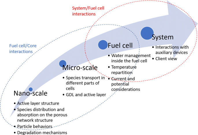
Interactions between the different scales of the FC system [42]
-
-
4.
High non-linearity and high uncertainty: nonlinear relationships exist in different physical domains in a FC systems. For instance, the polarization curve which describes the V-I property of a FC shows nonlinear characteristics (see Fig. 2). The nonlinear properties are also encountered when we try to build the fluidic model and thermal models [43]. The coupled high nonlinearities carry the difficulties particularly to the system modeling and control. As the performance of FC systems is dependent on many factors, from FCs themselves, the auxiliary subsystems, to the environment conditions, the high uncertainty of the FC behavior is usually faced. How to quantify the uncertainty properly is considered as a technical challenge.

In view of the above-mentioned difficulties, efforts can be taken to improve the FC performance systematically in the following directions.
Material and assembly improvement
Materials R&D is one critical element to highly improve the FC performance and push it into wider commercialization. Especially, the advanced materials are promising to play a key role to improve the durability and reduce the FC cost.
In [44], the important properties of the MEA for a PEMFC are summarized as follows.
-
high proton conductivity,
-
low electronic conductivity,
-
low fuel and oxidant permeability,
-
adequate electrochemical and chemical stability,
-
high thermal and hydrolytic stability,
-
significant dimensional and morphological stability,
-
adequate water transport properties,
-
good mechanical properties,
-
a sufficiently long lifetime,
-
a satisfactorily low cost.
In [44] and [45], the recent advances on membrane and catalyst, known as the two constituent components of FCs, are reviewed. Concerning the membrane material, it has been revealed that most alternative membranes are outperformed by Nafion membranes over an entire set of important properties. It may therefore be worthwhile to compromise on certain parameters to develop alternative specialized membranes [44]. It is also indicated in the same study that the two principle drawbacks of Nafion membrane, i.e., low methanol selectivity and the inability in elevated temperature, can be addressed by developing composite membranes. As for the catalyst, Pt-based catalysts still represent the most widely used catalysts due to their high activity. Efforts are being taken to reduce the Pt volume used in FCs without deteriorating the performance. Particular attention is paid to optimize (1) the intrinsic particle size of Pt particles, (2) the production of novel morphological motifs, as well as (3) the spatial distribution and dispersion of these particles onto an underlying support material [45]. Apart from the research on catalyst and membrane materials, the bipolar plate is one part that impacts the manufacturing cost and the FC performance substantially. Various materials, such as the graphite, metal, carbon, and polymer composites, can be the used for bipolar plate. Each type of material has its strengths and weaknesses. The key is to develop a balance between sufficient electrical conductivity and mechanical properties while allowing for rapid, continuous manufacturing [46–48].
Auxiliary components performance improvement
With the increased deployment of FCs in different applications, the industry has identified that a cost competitive, reliable and durable FC BoP system is equally important as the FCs. As shown in Fig. 7, the cost projections of 80 kW automotive FC system in 2017 assume that the BOP system contributes more than 55% of the total system cost [23]. The components needed to assemble the BoP system are not often commercially available. Some high-quality components, such as electronic valve, high-speed compressor, hydrogen circulating pump, humidifier, can only be fabricated by few companies in the worldwide scale [49].

Component cost of 80 kW automotive FC system at a production volume of 500,000 units/yr: a FC system; b FC stack [23]
Among the different BoP subsystems, air supply subsystem consists of compressor driven by electrical motor, optional expander, humidification, air filter and air cooler. The air supply system has a great impact on the stack performance, the overall system efficiency and cost [50]. As the core component, different types of compressors can be used to supply pressed air to the cathode. Compared with other displacement compressors (scroll compressor, lobe compressor, screw compressor, etc.) [51]. In [52], different air compressors’ performance and physical characteristics are compared.
Humidification system is an important auxiliary system for FC, which may influence the performance and durability of the FC. It is of great importance to choose proper humidification strategy for different applications. For example, for portable or vehicle applications, internal humidification may be preferable to reduce weight and space; while for stationary applications, sufficient humidification performance becomes more important, thus gas bubbling humidification or direct water injection method is more preferable. More details on FC humidification strategy can be found in the review paper [53].
Effective cooling is critical for safe and efficient operation of FC stacks with high power. Then the advantages, challenges and progress of various cooling techniques, including (i) cooling with heat spreaders (using high thermal conductivity materials or heat pipes), (ii) cooling with separate air flow, (iii) cooling with liquid (water or antifreeze coolant), and (iv) cooling with phase change (evaporative cooling and cooling through boiling), are systematically reviewed [54]. The further research needs in this area are identified in the same review paper.
The power conditioning subsystem for FC, also known as power converter, will be discussed in the following subsection dedicated to system integration.
Fuel cell system modeling
When an FC is operated in one operating condition, the electric chemical characteristics can be described using an equivalent circuit model. A typical circuit is shown in Fig. 8 and consists of two resistors (Rm and Rct), a capacitor (Cdl), and a non-linear impedance element (ZW). These components can be related to the different losses and electric-chemical processes [56].

Equivalent circuit of FC [55]
As the operation of FCs involves multi-physics which are coupled tightly, the modeling of FCs, from single molecular and pore-level to system level, has already been receiving attention from different research communities. Depending on the simplicity level, the FC models are classified into multi-dimensional numerical models and 0-dimensional control-oriented ones in this review.
In multi-dimensional models, notably the 2-D and 3-D ones, numerical studies are carried out to provide the detail of quantities that are difficult to capture in situ with regular measurement, such as the distributions of potential, temperature, reactant and current in the individual FCs and components [57–59].
The 3-D multi-phase computational fluid dynamics (CFD) model is widely adopted in optimizing the design of the single cell and the stack. It is known that the water management and thermal management are highly interrelated and the experimental study of the coupled managements is hard and costly. Developing model to optimize water and thermal management has thus been a popular and widely acceptable choice [60]. In order to reduce the cost of FC systems and hydrogen consumption, several recent works have been dedicated to implementing the multi-dimensional, multi-physics models of FC stack in real-time [61]. By using the FC real-time simulator, hardware-in-loop simulations can be carried out and the impacts of operating parameters and control laws can be studied in deep.
Multi-dimensional models are usually not suitable for the control design and the analysis in the system level, because in a classical control design, only limited measurable variables need to be controlled to the required values, and the detailed spacial distributions of these variables are not useful. Moreover, the multi-dimensional model is implemented with numerical calculation method which is time-consuming and not adapted to the control design. Even control oriented model is simplified from multi-dimensional models, many parameters still need to be known or identified in prior. For instance, in the most used V-I model, there are about 10 parameters to be identified, if an arbitrary FC is under study [62]. Apart from this, the detailed parameters on the internal sizes and characteristics of a studied FC should be known in prior to build the thermal and fluid models.
Until now, many engineers have confused on the models of the FCs or FC stacks with the ones of FC systems. A number of simulation plate-forms of some FC applications have been even built without considering the system dynamics. A few common used general control-oriented models have been proposed for instance in [63]. However, these models were built for some specific FC systems which are quantified with particular prior known parameters of both FCs and BoP subsystems. It is usually a hard or even impossible work to adapt these models to an arbitrary FC system. Other works focus on the models of one specific subsystem, and the coupling between the studied one and the other subsystems is often assumed to be weak. For instance, a control-oriented humidification model is proposed in [64]. Two different dynamic control-oriented thermal models are proposed in [64]. In [65] and [66], the model proposed in [63] is simplified to focus on air-fed control problem.
Modelling and simulation are effective tools for investigating the physical processes inside a FC. The early literature paid great attention to steady-state transport phenomena in the main components, which continues to be a focus of ongoing activities. There is, on the other hand, a growing interest in modelling other aspects of FC operation, such as transient performance, including freeze-start and start-up/shutdown processes [57]. Modeling FC degradation has been attracting more and more attention from both academic and industrial communities. Some simple degradation models have been proposed in the literature, for instance in [67] and [68]. However, due to the complex FC degradation mechanisms highly related operating conditions, there are relatively few PEMFC models that incorporate these degradation phenomena, which is somewhat surprising in view of their importance [57].
Advanced monitoring and measurements
To control and monitor FCs, different measurements should be acquired either online or offline. The measurements can be categorized into two classes, the regular in-situ measurements and those specific to FCs.
Among the regular in-situ measurements, the fluidic sensors can be installed along the both inlets and outlets of the reactants to measure the pressures and the flow rates, as shown in Fig. 9. The thermal measurements can be adopted at both the gas lines as shown in Fig. 9 apart from those used in the temperature management system. It should be noted that a certain number of thermal sensors can be put in the temperature management system to achieve a precise temperature control (shown in Fig. 10). In the electric circuit, the output current and stack voltage are two mandatory variables for the control and the monitoring of FC systems. Depending on the complexity of the system designs and the specific application requirements, the above mentioned measurements are partially equipped in some FC systems. For instance, the flow rate measurements are sometimes pruned in the applications where compact and economic designs are required.

Measurements in air fed and hydrogen fed lines [69]

Measurements in temperature management system [70]. T1, Tst, Tst, Tst, Tcw are the temperatures measured at different positions
The measurements specific to FC can be done using numerous experimental methods and/or using some specially designed sensors. Electrochemical impedance spectroscopy (EIS), linear sweep voltammetry (LSV) and cyclic voltammetry (CV) are three most efficient experimental characterizations apart from the commonly adopted characterization or polarization curve test [71]. Among them EIS characterization is the most attracting one regarding the abundant information that it can provide and the relatively easy implementation. EIS allows measuring the stack impedance by applying a small sinusoidal current signal on the FCs and measuring the corresponding stack voltage over a wide frequency range (from mHz to kHz). Impedance is thus obtained by dividing the alternating components of the stack voltage and current. The impedances over the test frequency range can be represented either in the form of real and imaginary parts (Nyquist plot) [72]. From the EIS curve, some features can be extracted and the variations of these features can be linked to the FC internal health conditions. As shown in Fig. 11, the EIS curves acquired in varied operating conditions are different. In view of the abundant information through EIS test, some recent works have been dedicated to realizing EIS test by using the DC/DC converter with specially designed control [73]. The application of LSV and CV tests on FC monitoring is discussed and summarized in [71].

EISs measured under different air stoichiometry (Stair) values
Apart from the specific experimental protocols for FCs, some particular sensors are adopted to realize the special measurements. In [74], the magnetic fields around a FC stack are measured using multiple magnetic sensors as shown in Fig. 12. With the measured magnetic fields, the internal current density, which is considered as the important data to know the internal condition of FCs, can be rebuilt using an inverse model [75]. The recovered current density is demonstrated to be consistent with the measured with invasive tool in the study. In [76], multichannel voltage sensors of giant magneto resistance (GMR) type are designed to measure the individual cell voltages regarding that the individual cell voltages show different magnitudes and behaviors in different operating conditions and fault conditions. An application-specific integrates circuit (ASIC) integrating the multi-channel GMR sensors and the computing unit is designed and shown in Fig. 13. In the last decade, many works have been carried out to develop the flexible micro sensors to access the local temperature, voltage and current inside the FCs [78, 79].

Magnetic sensors installation [74]

ASIC designed for monitoring individual FC voltages. (a) The architecture of the ASIC. (b) The appearance of the designed ASIC. [77]
Advanced diagnosis and prognosis methods
To improve the reliability and durability performance of FCs, it is intuitive to access the current health state of PEMFC and predict its evolution. This involves the topics of diagnosis and prognosis.
Fault diagnosis, dedicated to detecting, isolating, and analyzing different faults, has proved to be a crucial tool to keep the FC systems operating safely and efficiently and to mitigate performance degradation. The operation of a PEMFC system involves FCs and multiple subsystems where multiphyisics phenomena are interrelated. To accurately diagnose the faults occurring on the system level is not a trivial task. During the last decade, considerable attention has been focused on the fault diagnosis from different points of view. Many works have been developed to investigate the measurements or monitoring methods which can provide the fault sensitive information. While other works are focused on the diagnosis methodologies once the measurements are acquired. Among the most substantial approaches, model based fault diagnosis approaches have been proposed. A review of model based methods is available in [55]. Most of these approaches are based on some general input-output or state space models, which are usually developed from the physical and mathematical knowledge of the process [80]. In view of the difficulties on building a fault oriented model, the data-driven methodologies have also been studied in a number of studies [72, 81]. Although some interesting preliminary results have been proposed in the frame of data-driven diagnosis, for instance those summarized in the review paper [82], the online implementation and validation of those approaches in different real PEMFC systems have been rarely announced. To evaluate the diagnosis approaches, notably these for online diagnosis, several criteria have been proposed in [76].
Related to the diagnosis, prognosis, dedicated to predict the remaining useful life of the FCs, has been attracting increasing attention during the last years. Different types of approaches have been proposed for FC prognostics. Similarly to the diagnosis, the model-based approaches have been proposed when a physical degradation model is built. For instance, the authors of [83] propose to apply extended Kalman filter to track the deviations of global resistance and limiting current density, which are considered as the indicators reflecting the state of degradation. In [68], a physics-based, prognostic-oriented catalyst degradation model is built and an unscented Kalman filter is then applied to predict the trend of the evolution of the electro-chemical surface area. However, these proposed model-based approaches consider some specific operations and degradation factors, and the generalization performance might not be guaranteed.
The mechanisms of FC degradation are complex and highly dependent on the operating conditions [84]. An analytical degradation model with full consideration of all the degradation factors and the operating conditions is hard to build. For this reason, data-driven prognostics have become the concerns of most recent studies. Several studies based on machine learning techniques or other data-based techniques are proposed to trace the stack voltage evolution [85–87]. In these works, different machine learning models are trained to predict the trends of the FC voltage evolution. In [88], a review on the prognostic methods proposed for FCs was made. Some definitions relating to the prognosis, such as the end of life, were clarified in this review, and several candidates of health indicator and the criteria for evaluating the prognosis methods were also proposed in this paper.
One of the main problems of the prognosis for FCs is related to the lack of test and failure data. As the ageing degradation is dependent on the designs of the FCs and the FC systems, as well as the operating conditions, to explore the quantitative relation between the degradation rate and these coupling factors, a lot of long-term tests should be carried out on purpose. The general degradation physical or semi-empirical models, which take the micro-scale explanation of failure mechanisms and macro-scale operating conditions into consideration, are highly required. The prognosis should also be considered to link with the control strategy of the FC systems to mitigate the degradation rate.
System integration and control
The control of a FC system consists of two levels. The first level is dedicated to the controls of the auxiliary subsystems, including the thermal management control, water management control, reactant supplying control. The second level is involved when the FC system is integrated with the other components, such as the energy storage units and the power converters. In this level, the control is to coordinate the different sources in the hybrid FC systems.
The control methods proposed on the first level are reviewed in [89]. Among the proposed control methods, most are dedicated to the air fed subsystem control since the subsystem shows high-nonlinear behavior [65, 66]. The temperature and humidification controls have also begun to attract the attention of the control community [64, 90]. Some problems on the first level control are still open. First, the current studies focus still on the feed-back control with a fixed reference, while the control dedicated to enhancing the durability and tolerating certain recovery faults is still a fresh field, although several studies have been launched recently [91, 92]. Second, as the different control subsystems are coupled via the FC stack, the control should be designed in consideration of the interactions of the different subsystems. Third, in view of the difficulties on precise modeling an arbitrary FC system in the whole life-cycle, the robustness and adaptiveness of the control methods should be emphasized in practice.
FCs are usually applied with auxiliary storage units to obtain satisfactory dynamic responses and good energy management. The hybrid system, integrating FCs and the storage units, can be designed with different topologies and of different sizings depending on the applications. In most studies, the FC is proposed to be used with a single storage unit. The most used storages are the batteries and supercapacitors [93, 94]. In some studies, the hybrid energy storage systems, combing multiple storage units of different types are also proposed to gather the advantages of different storages [95]. The structure of multiple FC stacks instead of deploying only one stack has recently attracted increasing attention [96]. The multi-stack FC (MSFC) systems can provide more redundancy than single stack systems, so that the system reliability can be improved. The efficiency of MSFC systems can also be increased by optimally distributing the demanded power among different stacks [97]. DC/DC converter [98]. With the given system structure, the energy management strategy (EMS), dedicating to dispatching load power demand among different sources, becomes the key issue to realize the potential of the hybrid FC system. Different EMS approaches have been proposed to enhance the system efficiency and the durability of both the FCs and the storage units [99, 100]. As the different sources are interconnected through DC/DC converters, the EMS has to be realized via these converters. During the last two decades, intensive studies have been carried out to develop more compact, more efficient and more targeted DC/DC converter topologies and control methods [10, 13, 98, 101, 102].
Challenges of fCs based microgrids
As per the planning and operation requirements of modern distribution grids, it is urgently required to have rapid development of cutting-edge technologies for advancing grid operation towards higher reliability and resiliency. As commonly known, the electric grid is one of the most critical systems in everyday life. Furthermore, as the penetration level of renewable energy (e.g., solar, wind, etc.) increases rapidly, distribution grids, as the active and most significant ’grid-edge’ for renewable energy integration, play a critical role to bridge the grid backbone (i.e., transmission system) to the end-users [103, 104]. A safe, reliable and resilient distribution system is urgently needed to modernize the electric grid and ensure operational continuity. Specifically, the requirements of modern microgrids can be summarized as follows [11],
-
Self-healing
-
Consumer friendly
-
Resistant to physical and cyber attacks
-
Optimizes asset utilization which can be considered using FCs
-
Eco-friendly
-
The use of robust two-way communications, advanced sensors and distributed computing technology
-
Improve the efficiency, reliability and safety of power delivery and use.
However, there are enormous challenges in modern distribution system operation under both regular and extreme conditions [105, 106]. In particular, in normal operation of distribution systems, high penetration of renewable energy presents significant challenges (e.g., protection malfunction, voltage violation, etc.) to the legacy system, which was designed to only handle passive loads and networks [107]. More importantly, the distribution grid is also stressed out in extreme conditions, such as large-scale weather events (e.g., hurricane, flood, and other types of natural disasters). As stated in an event summary, recent hurricanes in United States (Irma, Harvey, etc.) caused a total loss of 1.25 billion hours of electricity. Moreover, natural disasters such as hurricanes can cause power outages for millions of customers across multiple states for an extended period of time. It is estimated that hurricanes Irma and Harvey have caused a total damage of over $200M in the past months [108].
Due to its cleanliness, high power density, and suitability for electricity and heat generation, FCs are gaining more and more popularity and being expected to playing an important role on improving the reliability, safety and resiliency of the modern distribution systems, notably microgrids [109]. However, FCs have not yet been applied sufficiently in microgrids regarding the maturity of FC technology. While the other distributed generators have been studied for long time [11]. This motivates the development of the FC technology on the one hand. On the other hand, the outstanding characteristics of FCs are promising to provide solutions to surmount the challenges of the microgrids. This section tries to summarize the ongoing research on FC based microgrids and the potential challenges.
System hybridization
An intuitive and straightforward solution for using renewable energy sources (RES) to enhance grid resiliency is to leverage distributed energy injection to mitigate power mismatch locally. In other words, microgrids can be implemented to coordinate local sources and loads [110–113]. However, given the stochasticity of many types of RES (e.g., solar, wind, etc.), the operational performance cannot be completely satisfactory; the integration of distributed energy resources (DERs) with more reliable power output is desired to alleviate the uncertainties in the supplied power and also support the energization of local loads, especially critical load infrastructures. Therefore, the deployment of FCs along with other controllable DERs (e.g., energy storage units (ESUs), etc.) serves as an effective and useful solution due to their reliable output power compared to other types of intermittent RES [114–116]. However, even though it is commonly known that FCs as well as ESUs can be used to mitigate the intermittency induced by stochastic RES, there are still concerns of system costs and potentially limited capacity of each individual unit. Solely relying on FCs may impose unavoidable cost increase, obstructing further popularization of FC technologies. To reduce the whole system cost, FCs can therefore be hybridized with the traditional RESs to provide more reliable energy. In the literature, PV/FC/battery microgrids have been considered as the most used hybrid ones [6]. The Wind/PV/FC microgrids are also studied in many studies [7].
In order to achieve a better energy storage flexibility, the electrolysers are also adopted in the microgrid to be able to store energy in the form of compressed hydrogen [117–119]. As FCs are just beginning to attract the attention in the microgrid research and very limited installed systems can provide practical references, the hybridization strategies need to be evaluated with different criteria, including those above mentioned and proposed for modern microgrids.
System control and energy management
When different topologies of microgrid are faced, the system sizing, modeling, control and energy management show up. Studies have been carried out in these directions, especially the EMS is one of the most attracting topics on FCs based microgrids [107, 120–122]. In different control framework, the problems are usually formulated in different manners subject to the objective functions and underlying controls. As noted by many researches, the current control and EMS methods should be improved subject to the more and more critical requirements on the microgrid reliability, safety and resiliency. Especially, the potential of FC based microgrids is expected to be realized through proposing more intelligent control and EMS.
-
1.
Multi-level control:
As shown in Fig. 14, the control of a microgrid could consist of the following levels:
-
(a)
Energy capture control.
Fig. 14 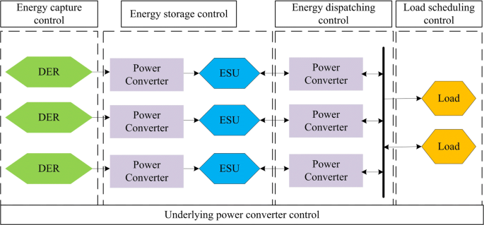
Multi-level control framework
-
(b)
Energy storage control.
-
(c)
Energy dispatching control.
-
(d)
Load scheduling control.
-
(e)
Underling power converter control.
Energy capture control is dedicated to the optimal operations of the DERs. In the FCs based microgrid, great attention should be taken to the control of FC plant, which is discussed in the previous section. As for the other DERs, notably PVs and wind turbines, many works have been proposed and being in process [123, 124].
In a microgrid, each energy storage system (ESS) has its own characteristics and capabilities referred to the relationship between energy and power density. The hybrid ESS, composed by multiple different types of storage units, benefits potentially a longer life span, higher efficiency and higher power density compared to battery-only storage [125]. In such case, the high number of constraints and variables to be optimized increases the complexity of the control problem, being the rationale to deploy advanced control algorithms [126]. Especially, the microgrids incorporating electrolyzers and hydrogen storage unit make the energy storage more complex than the other common used ESSs [127, 128].
Energy dispatching control of an microgrid is crucial for balancing the energy supply and demand sides, and should be designed to satisfy system constraints, to realize an economical, sustainable, and reliable operations [129]. Energy dispatching control also plays the important role on reactive power support and frequency regulation [130]. Actually, the energy dispatching control is the key element which is linked to other control blocks [131]. Different energy dispatching issues and methods are summarized in a recent review paper [13, 132].
To operate microgrids smarter, recent studies propose to implement demand side management (DSM) programs to manage the energy consumption of the consumers [133]. The DSM is dedicated not only to reducing the cost of the electricity, but also to increasing reliability and the resiliency of the microgrids [134]. It should be noted that the load characteristics of the load has been changing due to the wide penetration of the electric vehicles. It is important to well schedule the charging and the discharging of the EVs in order to achieve the higher reliability and stability microgrids and giving lower electricity prices to customers. Load characteristic [135, 136].
In the modern microgrids, the DERs, the ESSs, and the loads are mostly interconnected through power electronics interfaces. The above discussed controls are mostly realized by manipulating the power converters, which is considered as the underlying control. The underlying control layer is now also facing new challenges accompanying the developments of new power electronics components, such as those based on SiC. On the other hand, the communication between the underlying control and the higher level controls should be investigated to achieve an optimal overall control performance [137].
-
(a)
-
2.
Health management: Corresponding to the multi-level control design, the health management of microgrids should also be paid particular attention, and be designed with hierarchical structure. The health management includes the diagnosis, the prognosis and the targeted control dedicated to enhancing the reliability and durability of the component level and the system level. Lots of studies on health management have been carried out for one single component in the microgrid [138–140]. A systematical health management which can coordinate different faults and degradation issues is still missed. In fact, the research on health management methodologies has been receiving an increasing attention since the beginning of this decade. The topics on the health management of microgrids is becoming more and more attractive as the perfection of the theoretical base.
-
3.
Networked microgrids: Networked microgrids were proposed several years ago, with their tremendous advantages of enhancing distribution grid reliability and resiliency [141]. The major research interests of networked microgrids focus on: 1) cross-layer integration and optimization to dispatch grid assets within each microgrid [142, 143], and 2) resource planning to optimally size each microgrid and the controllable devices therein [144, 145]. Furthermore, as a natural extension of sectionalized distribution systems with networked microgrids, dynamic microgrids have been proposed and developed in the past years [146–148]. Particularly, dynamic microgrids can be seen as microgrids with dynamic boundaries, which features high operation flexibility and grid resiliency. Especially in extreme grid operation conditions, such as operation under power outages induced by natural disasters, dynamic microgrids can be implemented based on real-time operation conditions to pick up critical loads with flexible topology change. As enabling components in the context of dynamic microgrids, DERs, such as FCs, are used to energize local loads and multiple microgrids with dynamic boundaries are implemented surrounding these DERs. As mentioned above, DERs with reliable and stable output power are preferable to serve as major sources in dynamic microgrids, and FCs, as reliable power supplies, can be thereby used as this type of DERs. Meanwhile, given that FCs can be relatively movable compared to other types of DERs, they can be used in different locations to better support grid service restoration, which can further advance the concept of dynamic microgrids.

Conclusion
Combining the FC and microgrid technologies have shown various advantages. However, the nowadays studies on the microgrids deploying FCs are mostly implemented on simulation platforms or based on small-scale prototypes. As any new technology, the FCs based microgrids start to show out many opportunities. Meanwhile, the challenges are being encountered when efforts are taken to penetrate FCs in microgrids. In this paper, the corresponding studies in different domains are reviewed to reveal the challenges and possible research directions to realize the potential of the FC based microgrids. As shown in Fig. 15, the future work should be converged in the following aspects:
-
1.
FC technology need to be advanced by joining the efforts in multiple disciplines. Although the performance of FCs is often limited by the FC material and assembly techniques, it is oddly enough to see that the current short board of FC lies on the system integration and control level. In this view, more efforts should be taken to study FCs on system level compared to the research carried out during the last two decades.
Fig. 15 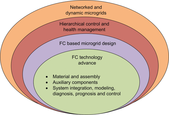
Multi-level control framework
-
2.
The design of FCs based microgrids should be enhanced through more real installations and case studies. FCs can be hybridized with other RESs and ESUs. Combing with electrolysers, the energy circulated in the microgrids can also be stored in the compressed hydrogen. All these structures merit the in deep and detailed evaluations and studies.
-
3.
As the other microgrid structures, continuous efforts should be taken to enhance the reliability, resiliency, safety and economic of the FCs based microgrid. To realize this, hierarchical control should be implemented on different levels. Relating to the control design, the health management of the microgrid, which did not receive enough attention, should be emphasized and the corresponding methodologies should be investigated in deep. To achieve higher-performance control and health management, the recent advances acquired in control, computing, communication domains are promising to be merged and applied.

Availability of data and materials
All the data used in this review are cited in the reference.
Notes
PEM in PEMFC can stand for either Proton Exchange Membrane or Polymer Electrolyte Membrane
Gibb free energy can be defined as the “energy available to do external work, neglecting any work done by changes in pressure and/or volume". In a FC the external work involves moving electrons round an external circuit
Abbreviations
- ASIC:
-
Application-specific integrates circuit
- BoP:
-
Balance of plant
- BP:
-
Bipolar plate
- CFD:
-
Computational fluid dynamics
- CHP:
-
Combined heat and power
- CL:
-
Catalyst layer
- CP:
-
Collector plate
- CV:
-
Cyclic voltammetry
- DOE:
-
Departement of energy
- DSM:
-
Demand side management
- EIS:
-
Electrochemical impedance spectroscopy
- EMS:
-
Energy management strategy
- ESS:
-
Energy storage system
- ESU:
-
Energy storage unit
- EU:
-
European Union
- FC:
-
Fuel cell
- GDL:
-
Gas diffusion layers
- GFC:
-
Gas flow channel
- GMR:
-
Giant magneto resistance
- LSV:
-
Linear sweep voltammetry
- MEA:
-
Membrane electrolyte assembly
- MSFC:
-
Multi-stack FC
- PEMFC:
-
Proton Exchange Membrane Fuel Cell
- PV:
-
Photovoltaic
- RES:
-
Renewable energy resource
- RES:
-
Renewable energy source
- V2G:
-
Vehicle-to-grid
References
Helm D. The european framework for energy and climate policies. Energy Policy. 2014; 64:29–35.
Gielen D, Saygin D, et al.Renewable Energy Prospects: United States of America. A Renewable Energy Roadmap, Remap 2030: Inter national Renewable Energy Agency; 2015. https://www.irena.org/media/Files/IRENA/Agency/Publication/2015/IRENA_REmap_USA_report_2015.ashx.
Qi Y, Ma L, Zhang H, Li H. Translating a global issue into local priority: China’s local government response to climate change. J Environ Dev. 2008; 17(4):379–400.
Ipakchi A, Albuyeh F. Grid of the future. IEEE Power Energy Mag. 2009; 7(2):52–62.
Ton DT, Smith MA. The us department of energy’s microgrid initiative. Electr J. 2012; 25(8):84–94.
Bigdeli N. Optimal management of hybrid pv/fuel cell/battery power system: A comparison of optimal hybrid approaches. Renew Sust Energ Rev. 2015; 42:377–93. https://doi.org/10.1016/j.rser.2014.10.032.
Wang C., Nehrir M. H.Power management of a stand-alone wind/photovoltaic/fuel cell energy system. IEEE Trans Energy Convers. 2008; 23(3):957–67. https://doi.org/10.1109/TEC.2007.914200.
Bai W, Abedi MR, Lee KY. Distributed generation system control strategies with pv and fuel cell in microgrid operation. Control Eng Pract. 2016; 53:184–93. https://doi.org/10.1016/j.conengprac.2016.02.002.
Alavi F, Lee EP, van de Wouw N, Schutter BD, Lukszo Z. Fuel cell cars in a microgrid for synergies between hydrogen and electricity networks. Appl Energy. 2017; 192:296–304. https://doi.org/10.1016/j.apenergy.2016.10.084.
Das V, Padmanaban S, Venkitusamy K. Recent advances and challenges of fuel cell based power system architectures and control – A review. Renew Sust Energ Rev. 2017; 73(January):10–18. https://doi.org/10.1016/j.rser.2017.01.148.
Yoldaş Y, l̇nen A, Muyeen SM, Vasilakos AV, l̇rfan A. Enhancing smart grid with microgrids: Challenges and opportunities. Renew Sust Energ Rev. 2017; 72:205–14. https://doi.org/10.1016/j.rser.2017.01.064.
Hirsch A, Parag Y, Guerrero J. Microgrids: A review of technologies, key drivers, and outstanding issues. Renew Sust Energ Rev. 2018; 90:402–411. https://doi.org/10.1016/j.rser.2018.03.040.
l̇nci M., Ömer Türksoy. Review of fuel cells to grid interface: Configurations, technical challenges and trends. J Clean Prod. 2019; 213:1353–70. https://doi.org/10.1016/j.jclepro.2018.12.281.
Li Z. Data-driven fault diagnosis for pemfc systems. PhD thesis. 2014. https://tel.archives-ouvertes.fr/tel-01275281/document.
Wee J-H. Contribution of fuel cell systems to co2 emission reduction in their application fields. Renew Sust Energ Rev. 2010; 14(2):735–44. https://doi.org/10.1016/j.rser.2009.10.013.
The Department of Energy Hydrogen and Fuel Cells Program Plan 2011. http://www.hydrogen.energy.gov/pdfs/program_plan2011.pdf.
Larminie J, Dicks A. Fuel Cell Systems Explained. Chichester: J. Wiley; 2003.
G Technical Services. Fuel Cell Handbook (Seventh Edition). Morgantown: U.S. Department of Energy, Office of Fossil Energy, National Energy Technology Laboratory; 2004. https://netl.doe.gov/sites/default/files/netl-file/FCHandbook7.pdf.
Yousfi-Steiner N, Moçotéguy P, Candusso D, Hissel D, Hernandez A, Aslanides A. A review on PEM voltage degradation associated with water management: Impacts, influent factors and characterization. J Power Sources. 2008; 183(1):260–74. https://doi.org/10.1016/j.jpowsour.2008.04.037.
Corbo P, Migliardini F, Veneri O. Hydrogen Fuel Cells for Road Vehicles. London: Springer; 2011.
Sammes N. Fuel Cell Technology: Reaching Towards Commercialization. Heidelberg: Springer; 2006.
E, 4Tech. The Fuel Cell Industry Review 2017. http://www.fuelcellindustryreview.com/. Accessed 4 Dec 2018.
Thompson ST, James BD, Huya-Kouadio JM, Houchins C, DeSantis DA, Ahluwalia R, Wilson AR, Kleen G, Papageorgopoulos D. Direct hydrogen fuel cell electric vehicle cost analysis: System and high-volume manufacturing description, validation, and outlook. J Power Sources. 2018; 399:304–13. https://doi.org/10.1016/j.jpowsour.2018.07.100.
2018 Cost Projections of PEM Fuel Cell Systems for Automobiles and Medium-Duty Vehicles. https://www.energy.gov/sites/prod/files/2018/04/f51/fcto_webinarslides_2018_costs_pem_fc_autos_trucks_042518.pdf. Accessed 23 Oct 2019.
2019 DOE Hydrogen and Fuel Cells Program Review Presentation. https://www.hydrogen.energy.gov/pdfs/review19/fc163_james_2019_o.pdf. Accessed 23 Oct 2019.
Saur G, Kurtz JM, Dinh HN, Ainscough CD, Onorato S. State-of-the-art fuel cell voltage durability and cost status: 2018 composite data products. Technical report. Natl Renew Energy Lab.(NREL), Golden, CO (United States). 2018.
Anastasiadis AG, Konstantinopoulos SA, Kondylis GP, Vokas GA, Papageorgas P. Effect of fuel cell units in economic and environmental dispatch of a microgrid with penetration of photovoltaic and micro turbine units. Int J Hydrogen Energy. 2017; 42(5):3479–86.
Huang X, Zhang Z, Jiang J. Fuel cell technology for distributed generation: an overview. In: Industrial Electronics, 2006 IEEE International Symposium On. IEEE: 2006. p. 1613–8. https://doi.org/10.1109/isie.2006.295713.
Van Wijk A, Verhoef L. Our Car as Power Plant. Amsterdam: Ios Press; 2014.
Dodds PE, Staffell I, Hawkes AD, Li F, Grünewald P, McDowall W, Ekins P. Hydrogen and fuel cell technologies for heating: A review. Int J Hydrogen Energy. 2015; 40(5):2065–83.
Barbir F. Transition to renewable energy systems with hydrogen as an energy carrier. Energy. 2009; 34(3):308–12.
NREL. Hydrogen Fuel Cell Power Demonstration for Sustainable Data Centers. https://www.nrel.gov/manufacturing/hydrogen-demonstration-data-center.html. Accessed 23 Oct 2019.
Ferenc J. Fuel cell generates clean, efficient energy for hospitals. https://www.hfmmagazine.com/articles/1988-fuel-cell-generates-clean-efficient-energy-for-hospitals. Accessed 15 Oct 2015.
Øystein Ulleberg, Nakken T., Eté A.The wind/hydrogen demonstration system at utsira in norway: Evaluation of system performance using operational data and updated hydrogen energy system modeling tools. Int J Hydrogen Energy. 2010; 35(5):1841–52. https://doi.org/10.1016/j.ijhydene.2009.10.077.
Zhang L, Gari N, Hmurcik LV. Energy management in a microgrid with distributed energy resources. Energy Convers Manag. 2014; 78:297–305.
Ma Z, Eichman J, Kurtz J. Fuel Cell Backup Power System for Grid-Service and Micro-Grid in Telecommunication Applications. In: ASME 2018 12th International Conference on Energy Sustainability. American Society of Mechanical Engineers: 2018. http://doi.org/10.1115/es2018-7184.
Robledo CB, Oldenbroek V, Abbruzzese F, van Wijk AJM. Integrating a hydrogen fuel cell electric vehicle with vehicle-to-grid technology, photovoltaic power and a residential building. Appl Energy. 2018; 215:615–29. https://doi.org/10.1016/j.apenergy.2018.02.038.
Ma R, Li Z, Breaz E, Pascal B, Gao F. Numerical Stiffness Analysis for Solid Oxide Fuel Cell Real-time Simulation Applications. IEEE Trans Energy Convers. 2018. https://doi.org/10.1109/TEC.2018.2849930.
Natarajan D, Van Nguyen T. A Two-Dimensional, Two-Phase, Multicomponent, Transient Model for the Cathode of a Proton Exchange Membrane Fuel Cell Using Conventional Gas Distributors. J Electrochem Soc. 2001; 148(12):1324. https://doi.org/10.1149/1.1415032https://doi.org/10.1149/1.1415032.
Pukrushpan JT, Peng H, Stefanopoulou AG. Control-Oriented Modeling and Analysis for Automotive Fuel Cell Systems. J Dyn Syst Meas Control. 2004; 126(1):14. https://doi.org/10.1115/1.1648308.
Wu J, Yuan XZ, Martin JJ, Wang H, Zhang J, Shen J, Wu S, Merida W. A review of pem fuel cell durability: Degradation mechanisms and mitigation strategies. J Power Sources. 2008; 184(1):104–19. https://doi.org/10.1016/j.jpowsour.2008.06.006.
Robin C, Gerard M, Franco AA, Schott P. Multi-scale coupling between two dynamical models for PEMFC aging prediction. Int J Hydrogen Energy. 2013; 38(11):4675–88. https://doi.org/10.1016/j.ijhydene.2013.01.040.
Luna J, Usai E, Husar A, Serra M. Nonlinear observation in fuel cell systems: A comparison between disturbance estimation and High-Order Sliding-Mode techniques. Int J Hydrogen Energy. 2016; 41(43):19737–48. https://doi.org/10.1016/j.ijhydene.2016.06.041.
Kraytsberg A., Ein-Eli Y.Review of Advanced Materials for Proton Exchange Membrane Fuel Cells. Energy Fuels. 2014; 28(12):7303–30. https://doi.org/10.1021/ef501977k.
Scofield ME, Liu H, Wong SS. A concise guide to sustainable PEMFCs: recent advances in improving both oxygen reduction catalysts and proton exchange membranes. Chem Soc Rev. 2015; 44(16):5836–60. https://doi.org/10.1039/c5cs00302d.
Cunningham B, Baird DG, Cunningham B. The development of economical bipolar plates for fuel cells. 2006:4385–4388. https://doi.org/10.1039/b611883f.
Shimpalee S, Lilavivat V, Mccrabb H, Khunatorn Y, Lee H, Lee W, Weidner JW. ScienceDirect Investigation of bipolar plate materials for proton exchange membrane fuel cells. Int J Hydrogen Energy. 2016; 41(31):13688–96. https://doi.org/10.1016/j.ijhydene.2016.05.163.
Hermann A, Chaudhuri T, Spagnol P. Bipolar plates for PEM fuel cells : A review. 2005; 30:1297–1302. https://doi.org/10.1016/j.ijhydene.2005.04.016.
Carlson E, Kopf P, Sinha J, Sriramulu S, Yang Y. Cost analysis of pem fuel cell systems for transportation: September 30, 2005. 2005. https://doi.org/10.2172/862302.
Wan Y, Guan J, Xu S. Improved empirical parameters design method for centrifugal compressor in PEM fuel cell vehicle application. Int J Hydrogen Energy. 2016; 42(8):5590–605. https://doi.org/10.1016/j.ijhydene.2016.08.162.
Zhao D, Zheng Q, Gao F, Bouquain D. ScienceDirect Disturbance decoupling control of an ultra-high speed centrifugal compressor for the air management of fuel cell systems. Int J Hydrogen Energy. 2013; 39(4):1788–98. https://doi.org/10.1016/j.ijhydene.2013.11.057.
Yu W, Sichuan X, Ni H. Air compressors for fuel cell vehicles: An systematic review. SAE Int J Altern Powertrains. 2015; 4(1):115–22.
Chang Y, Qin Y, Yin Y, Zhang J, Li X. Humidification strategy for polymer electrolyte membrane fuel cells – A review. Appl Energy. 2018; 230(August):643–62. https://doi.org/10.1016/j.apenergy.2018.08.125.
Zhao J, Jian Q, Luo L, Huang B, Cao S, Huang Z. Dynamic behavior study on voltage and temperature of proton exchange membrane fuel cells. Appl Therm Eng. 2018; 145(August):343–51. https://doi.org/10.1016/j.applthermaleng.2018.09.030.
Petrone R, Zheng Z, Hissel D, Péra MC, Pianese C, Sorrentino M, Becherif M, Yousfi-Steiner N. A review on model-based diagnosis methodologies for PEMFCs. Int J Hydrogen Energy. 2013; 38(17):7077–91. https://doi.org/10.1016/j.ijhydene.2013.03.106.
Yuan X, Wang H, Sun JC, Zhang J. AC impedance technique in PEM fuel cell diagnosis - A review. Int J Hydrogen Energy. 2007; 32:4365–80. https://doi.org/10.1016/j.ijhydene.2007.05.036.
Shah AA, Luo KH, Ralph TR, Walsh FC. Recent trends and developments in polymer electrolyte membrane fuel cell modelling. Electrochim Acta. 2011; 56(11):3731–57. https://doi.org/10.1016/j.electacta.2010.10.046.
Wang C-Y. Fundamental models for fuel cell engineering. Chem Rev. 2004; 104(10):4727–66. https://doi.org/10.1021/cr020718s. PMID: 15669167.
Weber AZ, Newman J. Modeling transport in polymer-electrolyte fuel cells. Chem Rev. 2004; 104(10):4679–726. https://doi.org/10.1021/cr020729l. PMID: 15669166. https://doi.org/10.1021/cr020729l.
Zhang G, Jiao K. Multi-phase models for water and thermal management of proton exchange membrane fuel cell: A review. J Power Sources. 2018; 391:120–33. https://doi.org/10.1016/j.jpowsour.2018.04.071.
Ma R, Li Z, Breaz E, Pascal B, Gao F. Numerical stiffness analysis for solid oxide fuel cell real-time simulation applications. Trans Energy Convers, IEEE. 2018:1–1. https://doi.org/10.1109/TEC.2018.2849930.
Priya K, Sathishkumar K, Rajasekar N. A comprehensive review on parameter estimation techniques for Proton Exchange Membrane fuel cell modelling. Renew Sust Energ Rev. 2018; 93(May):121–44. https://doi.org/10.1016/j.rser.2018.05.017.
Pukrushpan JT, Stefanopoulou AG, Peng H. Control of Fuel Cell Power Systems: Principles, Modeling, Analysis and Feedback Design. London: Springer; 2004.
Solsona M, Kunusch C, Ocampo-Martinez C. Control-oriented model of a membrane humidifier for fuel cell applications. Energy Convers Manag. 2017; 137:121–9. https://doi.org/10.1016/j.enconman.2017.01.036.
Chen J, Liu Z, Wang F, Ouyang Q, Su H. Optimal oxygen excess ratio control for PEM fuel cells. IEEE Trans Control Syst Technol. 2018; 26(5):1711–21. https://doi.org/10.1109/TCST.2017.2723343.
Liu J, Luo W, Yang X, Wu L. Robust Model-Based Fault Diagnosis for PEM Fuel Cell Air-Feed System. IEEE Trans Ind Electron. 2016; 63(5):3261–70. https://doi.org/10.1109/TIE.2016.2535118.
Pei P, Chang Q, Tang T. A quick evaluating method for automotive fuel cell lifetime. Int J Hydrogen Energy. 2008; 33(14):3829–36. https://doi.org/10.1016/j.ijhydene.2008.04.048.
Zhang X, Pisu P. An unscented kalman filter based approach for the health-monitoring and prognostics of a polymer electrolyte membrane fuel cell. Annu Conf Prognostics Health Manag Soc 2012. 2012; 3:1–9.
Candusso D, De Bernardinis A, Péra M-C, Harel F, François X, Hissel D, Coquery G, Kauffmann J-M. Fuel cell operation under degraded working modes and study of diode by-pass circuit dedicated to multi-stack association. Energy Convers Manag. 2008; 49(4):880–95. https://doi.org/10.1016/j.enconman.2007.10.007.
Hu P, Cao GY, Zhu XJ, Hu M. Coolant circuit modeling and temperature fuzzy control of proton exchange membrane fuel cells. Int J Hydrogen Energy. 2010; 35(17):9110–23. https://doi.org/10.1016/j.ijhydene.2010.06.046.
Wasterlain S, Candusso D, Harel F, Hissel D, Franc X. Development of new test instruments and protocols for the diagnostic of fuel cell stacks. J Power Sources. 2011; 196:5325–33. https://doi.org/10.1016/j.jpowsour.2010.08.029.
Zheng Z, Péra M-C, Hissel D, Becherif M, Agbli K-S, Li Y. A double-fuzzy diagnostic methodology dedicated to online fault diagnosis of proton exchange membrane fuel cell stacks. J Power Sources. 2014; 271:570–81. https://doi.org/10.1016/j.jpowsour.2014.07.157.
Wang H, Gaillard A, Hissel D. Online electrochemical impedance spectroscopy detection integrated with step-up converter for fuel cell electric vehicle. Int J Hydrogen Energy. 2019; 44(2):1110–21. https://doi.org/10.1016/j.ijhydene.2018.10.242.
Le Ny M. Diagnostic non invasif de piles à combustible par mesure du champ magnétique proche: Department of Materials Mechanics Energetics and Environment, Université de Grenoble; 2012. https://tel.archives-ouvertes.fr/tel-00844407v2/document.
Le Ny M, Chadebec O, Cauffet G, Dedulle JM, Bultel Y, Rosini S, Fourneron Y, Kuo-Peng P. Current distribution identification in fuel cell stacks from external magnetic field measurements. IEEE Trans Magn. 2013; 49(5):1925–8. https://doi.org/10.1109/TMAG.2013.2239967.
Li Z, Outbib R, Giurgea S, Hissel D, Giraud A, Couderc P. Fault diagnosis for fuel cell systems: A data-driven approach using high-precise voltage sensors. Renew Energy. 2018. https://doi.org/10.1016/j.renene.2018.09.077.
Li Z, Outbib R, Giurgea S, Hissel D, Jemei S, Giraud A, Rosini S. Online implementation of svm based fault diagnosis strategy for pemfc systems. Appl Energy. 2016; 164:284–93. https://doi.org/10.1016/j.apenergy.2015.11.060.
Lee CY, Chiang YC, Weng FB, Li SC, Wu PH, Yueh HI. Flexible micro temperature, voltage and current sensors for local real-time microscopic diagnosis inside high temperature proton exchange membrane fuel cell stack. Renew Energy. 2017; 108:126–31. https://doi.org/10.1016/j.renene.2017.02.015.
Lee C-Y, Lee Y-M. In-situ diagnosis of local fuel cell performance using novel micro sensors. Int J Hydrogen Energy. 2012; 37(5):4448–56. https://doi.org/10.1016/j.ijhydene.2011.11.098.
Ding SX. Model-based Fault Diagnosis Techniques, vol. 2013. London: Springer; 2008.
Li Z, Outbib R, Giurgea S, Hissel D, Li Y. Fault detection and isolation for polymer electrolyte membrane fuel cell systems by analyzing cell voltage generated space. Appl Energy. 2015; 148:260–72. https://doi.org/10.1016/j.apenergy.2015.03.076.
Zheng Z, Petrone R, Péra MC, Hissel D, Becherif M, Pianese C, Yousfi Steiner N, Sorrentino M. A review on non-model based diagnosis methodologies for PEM fuel cell stacks and systems. Int J Hydrogen Energy. 2013; 38(21):8914–26. https://doi.org/10.1016/j.ijhydene.2013.04.007.
Bressel M, Hilairet M, Hissel D, Bouamama BO. Remaining useful life prediction and uncertainty quantification of proton exchange membrane fuel cell under variable load. IEEE Trans Ind Electron. 2016; 63(4):2569–77. https://doi.org/10.1109/TIE.2016.2519328.
Lim C, Ghassemzadeh L, Van Hove F, Lauritzen M, Kolodziej J, Wang G, Holdcroft S, Kjeang E. Membrane degradation during combined chemical and mechanical accelerated stress testing of polymer electrolyte fuel cells. J Power Sources. 2014; 257:102–10.
Silva RE, Gouriveau R, Jemeï S, Hissel D, Boulon L, Agbossou K, Steiner NY. Proton exchange membrane fuel cell degradation prediction based on adaptive neuro-fuzzy inference systems. Int J Hydrogen Energy. 2014; 39(21):11128–44.
Javed K, Gouriveau R, Zerhouni N, Hissel D. Improving accuracy of long-term prognostics of pemfc stack to estimate remaining useful life. In: 2015 IEEE International Conference on Industrial Technology (ICIT): 2015. p. 1047–52. https://doi.org/10.1109/ICIT.2015.7125235.
Morando S, Jemei S, Gouriveau R, Zerhouni N, Hissel D. Fuel cells prognostics using echo state network. In: IECON 2013 - 39th Annual Conference of the IEEE Industrial Electronics Society: 2013. p. 1632–7. https://doi.org/10.1109/IECON.2013.6699377.
Jouin M, Bressel M, Morando S, Gouriveau R, Hissel D, Péra MC, Zerhouni N, Jemei S, Hilairet M, Ould Bouamama B. Estimating the end-of-life of PEM fuel cells: Guidelines and metrics. Appl Energy. 2016; 177:87–97. https://doi.org/10.1016/j.apenergy.2016.05.076.
Daud WRW, Rosli RE, Majlan EH, Hamid SAA, Mohamed R, Husaini T. PEM fuel cell system control: A review. Renew Energy. 2017; 113:620–38. https://doi.org/10.1016/j.renene.2017.06.027.
Rojas JD, Kunusch C, Ocampo-Martinez C, Puig V. Control-Oriented Thermal Modeling Methodology for Water-Cooled PEM Fuel-Cell-Based Systems. IEEE Trans Ind Electron. 2015; 62(8):5146–54. https://doi.org/10.1109/TIE.2015.2405332.
Wu X, Zhou B. Fault tolerance control for proton exchange membrane fuel cell systems. J Power Sources. 2016; 324:804–29. https://doi.org/10.1016/j.jpowsour.2016.05.066.
Bressel M, Hilairet M, Hissel D, Bouamama BO. Model-based aging tolerant control with power loss prediction of proton exchange membrane fuel cell. Int J Hydrogen Energy. 2018. https://doi.org/10.1016/j.ijhydene.2018.11.219.
González EL, Cuesta JS, Fernandez FJV, Llerena FI, Carlini MAR, Bordons C, Hernandez E, Elfes A. Experimental evaluation of a passive fuel cell/battery hybrid power system for an unmanned ground vehicle. Int J Hydrogen Energy. 2019; 44(25):12772–82. https://doi.org/10.1016/j.ijhydene.2018.10.107. Special Issue on Selected Contributions from the European Hydrogen Energy Conference 2018. Málaga, Spain. March 14th - 16th.
Fathabadi H. Fuel cell hybrid electric vehicle (FCHEV): Novel fuel cell/SC hybrid power generation system. Energy Convers Manag. 2018; 156(October 2017):192–201. https://doi.org/10.1016/j.enconman.2017.11.001.
Li Q, Chen W, Liu Z, Li M, Ma L. Development of energy management system based on a power sharing strategy for a fuel cell-battery-supercapacitor hybrid tramway. J Power Sources. 2015; 279:267–280. https://doi.org/10.1016/j.jpowsour.2014.12.042.
Marx N, Boulon L, Gustin F, Hissel D, Agbossou K. A review of multi-stack and modular fuel cell systems: Interests, application areas and on-going research activities. Int J Hydrogen Energy. 2014; 39(23):12101–11. https://doi.org/10.1016/j.ijhydene.2014.05.187 Review.
Marx N, Hissel D, Gustin F, Boulon L, Agbossou K. On the sizing and energy management of an hybrid multistack fuel cell – Battery system for automotive applications. Int J Hydrogen Energy. 2017; 42(2):1518–26. https://doi.org/10.1016/j.ijhydene.2016.06.111.
Kolli A, Gaillard A, De Bernardinis A, Bethoux O, Hissel D, Khatir Z. A review on DC/DC converter architectures for power fuel cell applications. Energy Convers Manag. 2015; 105:716–30. https://doi.org/10.1016/j.enconman.2015.07.060.
Sulaiman N., Hannan M. A., Mohamed A., Ker P. J., Majlan E. H., Wan Daud W. R.Optimization of energy management system for fuel-cell hybrid electric vehicles: Issues and recommendations. Appl Energy. 2018; 228(May):2061–79. https://doi.org/10.1016/j.apenergy.2018.07.087.
Xu L, Ouyang M, Li J, Yang F, Lu L, Hua J. Application of Pontryagin’s Minimal Principle to the energy management strategy of plugin fuel cell electric vehicles. Int J Hydrogen Energy. 2013; 38(24):10104–15. https://doi.org/10.1016/j.ijhydene.2013.05.125.
Ahmed OA, Bleijs JAM. An overview of dc–dc converter topologies for fuel cell-ultracapacitor hybrid distribution system. Renew Sust Energ Rev. 2015; 42:609–26. https://doi.org/10.1016/j.rser.2014.10.067.
Mane S, Mejari M, Kazi F, Singh N. Improving lifetime of fuel cell in hybrid energy management system by lure–lyapunov-based control formulation. IEEE Trans Ind Electron. 2017; 64(8):6671–9. https://doi.org/10.1109/TIE.2017.2696500.
Apostolopoulou D, Bahramirad S, Khodaei A. The interface of power: Moving toward distribution system operators. IEEE Power Energy Mag; 14(3):46–51.
Wang J, Chen C, Lu X. Guidelines for Implementing Advanced Distribution Management Systems-Requirements for DMS Integration with DERMS and Microgrids. United States; 2015. https://doi.org/10.2172/1212266.
Siano P. Demand response and smart grids—a survey. Renew Sust Energ Rev. 2014; 30:461–78. https://doi.org/10.1016/j.rser.2013.10.022.
Ipakchi A, Farrokh A. Grid of the future. IEEE Power Energy Mag; 7(2):52–62.
Naidu BR, Panda G, Siano P. A self-reliant dc microgrid: Sizing, control, adaptive dynamic power management, and experimental analysis. IEEE Trans Ind Inform. 2018; 14(8):3300–13. https://doi.org/10.1109/TII.2017.2780193.
Hurricanes Nate, Maria, Irma, and Harvey Situation Reports. https://www.energy.gov/ceser/downloads/hurricanes-nate-maria-irma-and-harvey-situation-reports. Accessed 23 Oct 2019.
Ghazanfari A, Hamzeh M, Mokhtari H, Karimi H. Active power management of multihybrid fuel cell/supercapacitor power conversion system in a medium voltage microgrid. IEEE Trans Smart Grid. 2012; 3(4):1903–10. https://doi.org/10.1109/TSG.2012.2194169.
Hatziargyriou N, Hiroshi A, Iravani R, Marnay C. Microgrids. IEEE Power Energy Mag; 5(4):78–94.
Guerrero JM, Vasquez JC, Matas J, Vicuña LGD, Castilla M. Hierarchical control of droop-controlled ac and dc microgrids—a general approach toward standardization. IEEE Trans Ind Electron; 58(1):158–72.
Lopes JAP, Moreira CL, Madureira AG. Defining control strategies for microgrids islanded operation. IEEE Trans Power Syst; 21(2):916–24.
Rocabert J, Alvaro L, Blaabjerg F, Rodriguez P. Control of power converters in ac microgrids. IEEE Trans Power Electron; 27(11):4734–49.
Wang C, Nehrir H. power management of a stand-alone wind/photovoltaic/fuel cell energy system. IEEE Trans Energy Convers. 2008; 23(3):957–67. https://doi.org/10.1109/pes.2008.4596178.
Nelson DB, Nehrir MH, Wang C. Unit sizing and cost analysis of stand-alone hybrid wind/pv/fuel cell power generation systems. Renew Energy; 31(10):1641–56.
Agbossou K, Chahine R, Hamelin J, Laurencelle F, Anouar A, St-Arnaud J-M, Bose TK. Renewable energy systems based on hydrogen for remote applications. J Power Sources; 96(1):168–72.
Esmaeilian HR, Fadaeinedjad R. Resolving power quality issues raised by aerodynamic aspects of wind turbine in isolated microgrids using fuel cell/electrolyzer system. IEEE Trans Sustain Energy. 2016; 7(3):1274–83. https://doi.org/10.1109/TSTE.2016.2544102.
Valverde L, Bordons C, Rosa F. Integration of fuel cell technologies in renewable-energy-based microgrids optimizing operational costs and durability. IEEE Trans Ind Electron. 2016; 63(1):167–77. https://doi.org/10.1109/TIE.2015.2465355.
Zhang L., Xiang J. The performance of a grid-tied microgrid with hydrogen storage and a hydrogen fuel cell stack. Energy Convers Manag. 2014; 87:421–7. https://doi.org/10.1016/j.enconman.2014.07.045.
Jain S, Jiang J, Huang X, Stevandic S. Modeling of fuel-cell-based power supply system for grid interface. IEEE Trans Ind Appl. 2012; 48(4):1142–53. https://doi.org/10.1109/TIA.2012.2199454.
Sekhar PC, Mishra S. Storage free smart energy management for frequency control in a diesel-pv-fuel cell-based hybrid ac microgrid. IEEE Trans Neural Netw Learn Syst. 2016; 27(8):1657–71. https://doi.org/10.1109/TNNLS.2015.2428611.
Obara S, Sato K, Utsugi Y. Study on the operation optimization of an isolated island microgrid with renewable energy layout planning. Energy. 2018; 161:1211–25. https://doi.org/10.1016/j.energy.2018.07.109https://doi.org/10.1016/j.energy.2018.07.109.
Chiu C-S. Ts fuzzy maximum power point tracking control of solar power generation systems. IEEE Trans Energy Convers. 2010; 25(4):1123–32.
Morren J, De Haan SW, Kling WL, Ferreira J. Wind turbines emulating inertia and supporting primary frequency control. IEEE Trans Power Syst. 2006; 21(1):433–4.
Song Z, Hofmann H, Li J, Hou J, Han X, Ouyang M. Energy management strategies comparison for electric vehicles with hybrid energy storage system. Appl Energy. 2014; 134:321–331.
Garcia-Torres F, Valverde L, Bordons C. Optimal load sharing of hydrogen-based microgrids with hybrid storage using model-predictive control. IEEE Trans Ind Electron. 2016; 63(8):4919–28. https://doi.org/10.1109/TIE.2016.2547870.
Han Y, Zhang G, Li Q, You Z, Chen W, Liu H. Hierarchical energy management for pv/hydrogen/battery island dc microgrid. Int J Hydrogen Energy. 2018. https://doi.org/10.1016/j.ijhydene.2018.08.135.
Garcia-Torres F, Bordons C. Optimal economical schedule of hydrogen-based microgrids with hybrid storage using model predictive control. IEEE Trans Ind Electron. 2015; 62(8):5195–207. https://doi.org/10.1109/TIE.2015.2412524.
Hatziargyriou N. Microgrids: Architectures and Control. London: John Wiley & Sons; 2014.
Kayalvizhi S, Kumar DMV. Load frequency control of an isolated micro grid using fuzzy adaptive model predictive control. IEEE Access. 2017; 5:16241–51. https://doi.org/10.1109/ACCESS.2017.2735545.
Alipour M., Mohammadi-Ivatloo B., Zare K.Stochastic scheduling of renewable and chp-based microgrids. IEEE Trans Ind Inform. 2015; 11(5):1049–58. https://doi.org/10.1109/TII.2015.2462296.
Zia M. F., Elbouchikhi E., Benbouzid M.Microgrids energy management systems: A critical review on methods, solutions, and prospects. Appl Energy. 2018; 222:1033–55. https://doi.org/10.1016/j.apenergy.2018.04.103.
Masters GM. Renewable and Efficient Electric Power Systems. Hoboken: John Wiley & Sons; 2013.
Kakran S, Chanana S. Smart operations of smart grids integrated with distributed generation: A review. Renew Sust Energ Rev. 2018; 81:524–35. https://doi.org/10.1016/j.rser.2017.07.045.
Cingoz F, Elrayyah A, Sozer Y. Optimized resource management for pv–fuel-cell-based microgrids using load characterizations. IEEE Trans Ind Appl. 2016; 52(2):1723–35. https://doi.org/10.1109/TIA.2015.2499287.
Tushar MHK, Assi C, Maier M, Uddin MF. Smart microgrids: Optimal joint scheduling for electric vehicles and home appliances. IEEE Trans Smart Grid. 2014; 5(1):239–50.
Cai N., Mitra J.A multi-level control architecture for master-slave organized microgrids with power electronic interfaces. Electr Power Syst Res. 2014; 109:8–19. https://doi.org/10.1016/j.epsr.2013.11.027.
Vian JL, Mansouri AR, Elangovan R, Borumand MM, Abdel-Motagaly K. Health management of rechargeable batteries. Google Patents. 2014. Patent 8, US, 890,480.
Kandukuri ST, Klausen A, Karimi HR, Robbersmyr KG. A review of diagnostics and prognostics of low-speed machinery towards wind turbine farm-level health management. Renew Sust Energ Rev. 2016; 53:697–708.
Riley D, Johnson J. Photovoltaic prognostics and heath management using learning algorithms. In: Photovoltaic Specialists Conference (PVSC), 2012 38th IEEE. IEEE: 2012. p. 001535–9. https://doi.org/10.1109/pvsc.2012.6317887.
Li Z, Shahidehpour M, Aminifar F, Alabdulwahab A, Al-Turki Y. Networked microgrids for enhancing the power system resilience. Proc IEEE. 2017; 105(7):1289–310. https://doi.org/10.1109/jproc.2017.2685558.
Wang Z, Chen B, Wang J, Begovic MM, Chen C. Coordinated energy management of networked microgrids in distribution systems. IEEE Trans Smart Grid; 6(1):45–53. https://doi.org/10.1109/pesgm.2015.7286148.
Lv T, Qian A. Interactive energy management of networked microgrids-based active distribution system considering large-scale integration of renewable energy resources. Appl Energy. 2016; 163:408–22.
Wang Z, Chen B, Wang J, Kim J, Begovic M. Robust optimization based optimal dg placement in microgrids. IEEE Trans Smart Grid; 5(5):2173–82.
Khodaei A, Shahidehpour M. Microgrid-based co-optimization of generation and transmission planning in power systems. IEEE Trans Power Syst. 2018; 28(2):1582–90. https://doi.org/10.1109/tpwrs.2012.2224676.
Nassar ME, Salama MM. Adaptive self-adequate microgrids using dynamic boundaries. IEEE Trans Smart Grid. 2016; 7(1):105–13. https://doi.org/10.1109/tsg.2015.2420115.
Kim Y, Wang J, Lu X. A framework for load service restoration using dynamic change in boundaries of advanced microgrids with synchronous-machine dgs. IEEE Trans Smart Grid. 2018; 9(4):3676–90. https://doi.org/10.1109/tsg.2016.2638854.
Du Y, Lu X, Wang J, Lukic S. Distributed secondary control strategy for microgrid operation with dynamic boundaries. IEEE Trans Smart Grid. 2019; 10(5):5269–82. https://doi.org/10.1109/tsg.2018.2879793.
Acknowledgements
The PhD thesis of ZL entitled “Data-driven fault diagnosis for PEMFC systems” has been used and adapted to provide the background of FCs. The sources of figures and tables are acknowledged in the corresponding legends and captions.
Funding
Not applicable.
Author information
Authors and Affiliations
Contributions
ZL organized the whole drafting process and the submission. ZL, ZZ, and LX investigated and drafted the sections on fuel cells. XL and ZZ were in charge of the sections on microgrid. All the authors contributed to the common parts on the integration of fuel cells in microgrids. All authors contributed to write and revise the paper. All authors read and approved the final manuscript.
Corresponding author
Ethics declarations
Competing interests
The authors declare that they have no competing interests.
Additional information
Publisher’s Note
Springer Nature remains neutral with regard to jurisdictional claims in published maps and institutional affiliations.
Rights and permissions
Open Access This article is distributed under the terms of the Creative Commons Attribution 4.0 International License (http://creativecommons.org/licenses/by/4.0/), which permits unrestricted use, distribution, and reproduction in any medium, provided you give appropriate credit to the original author(s) and the source, provide a link to the Creative Commons license, and indicate if changes were made. The Creative Commons Public Domain Dedication waiver (http://creativecommons.org/publicdomain/zero/1.0/) applies to the data made available in this article, unless otherwise stated.
About this article

Cite this article
Li, Z., Zheng, Z., Xu, L. et al. A review of the applications of fuel cells in microgrids: opportunities and challenges. BMC Energy 1, 8 (2019). https://doi.org/10.1186/s42500-019-0008-3
Received:
Accepted:
Published:
DOI: https://doi.org/10.1186/s42500-019-0008-3